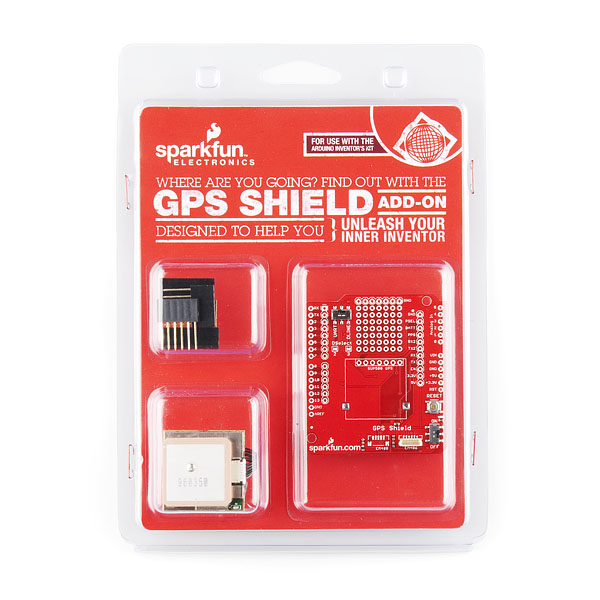
A connector for the popular EM-406 GPS receiver is populated on the board, and footprints for EM-408 and EB-85A connectors are also made available (connectors are not included and can be found below in the related items). There is also a spot for the UP501 GPS module. The regular GPS pins (RX, TX, PPS, etc.) are also broken out to a 10-pin 0.1" pitch header, and a small protoyping area is also provided.
The DLINE/UART switch switches the GPS module's input/output between Arduino's standard TX/RX pins or any digital pins on the Arduino (default setting uses pins 3 and 2 connected to TX and RX, respectively). The DLINE/UART switch must be set to DLINE in order to upload code through the Arduino IDE.
The shield also includes the footprint for a 12mm coin cell battery holder to provide battery backup to the optional EB-85A GPS module.An ON/OFF switch is included which controls power to the GPS module. Additionally, the Arduino reset switch is also brought out.
Includes:
• GPS Shield
• EM-406 GPS Module
• EM-406 Interface Cable
• Set of Stackable Headers
Features:
• EM-406 connector populated
• EM-408 and EB-85A connector footprints provided and connected for optional use
• UP501 connector and footprint
• Coin cell battery socket footprint provided and connected for optional battery backup of EB-85A GPS module
• Standard Arduino sized shield
• Prototyping area
• GPS serial and PPS signals broken out to a 0.1" header for additional device connections
• Arduino reset button
• DLINE/UART switch controls serial communications
• ON/OFF switch controls power to GPS module
Documents:
•Schematic
•Eagle Files
•GPS Quickstart Guide
•Assembly Guide
•Example Sketch
|


